3D Fault Model: an example
Creating a 3D Fault Model is always complicated and subject to interpretation. In many circumstances faults cannot directly be recorded and are inferred. In addition, faults are generally not nicely behaved surfaces that simply divide a model area into two. In the past that was how faults were treated in GEOREKA. However, with some newly added tools we have been able to provide a more flexible, yet still simpler way to create faulted geology models, making the modelling experience more fun and efficient. This allows users to define faults to terminate against other faults, cross-cutting faults, or normal fault behaviour that is generally associated with a 3D faulted geology model.
The Model descriptor is a recently added tool (from Version 4). It gives the user the ability to build fault zones by specifying relationships between domains separated by faults. To this end sub-domains are created from each fault. Within each sub-domain modelling proceeds as if modelling normal domains. Adding the ability to create fault blocks this way greatly improves flexibility and efficiency for more complex models by allowing the user to specify a relative age to faults. The result is that faults will only affect older units, but not the younger units, giving full control to the user.
Fault surfaces
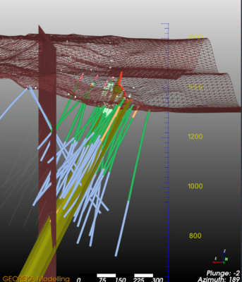
As a first step in setting up a modelling workflow the new tools require a definition of the fault blocks as sub-domains. The fault blocks are defined in a similar fashion to geological units. To illustrate, below, the fault blocks are defined by fault surfaces. These fault surfaces can be created from topography traces, drill core samples or other means. We will not cover that step in this article.
The faults are converted to functions by one of two options: 1) create a signed distance function for each fault, or 2) construct a Machine Learning classifier. The first can be a bit more accurate to honour the original surface, but is prone to errors in the triangulated surface itself (self-intersections, jumps, gaps etc.). The second option will generally produce very good results, but can produce smoothed results for some surfaces.
Fault relationships
The most important aspect in 3D modelling faulted geology is by defining the relationships between faults. When they are near-parallel the step is fairly simple. But what happens when faults cross-cut or terminate against another? Here we give an example on how that would work in GEOREKA.
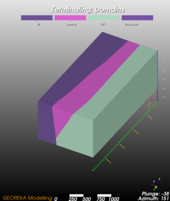
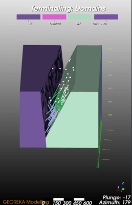
First we will demonstrate how to model a fault terminating against another. This is relatively simple. In the model descriptor we select the faults, represented by the functions EF_fun and WF_fun, to use and select the fault against which to terminate first. This divides the whole model area into 2 zone (EF and the rest). Within the second zone, we then use the 2nd fault to divide the whole area into 3 zones (EF, Central and WF). The Eastern side of the East fault is not affected, whereas the western side if faulted again using the West fault (see images on the side).

Real-world example of fault blocks
The above examples only show how fault blocks can be created before the actual 3d geological modelling. In the next example a fault block model is create from similar data and used as input for the geological model.
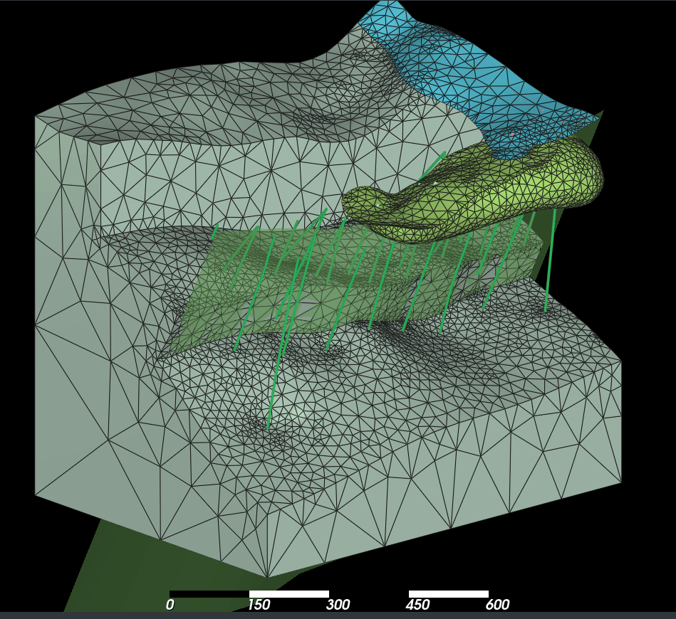
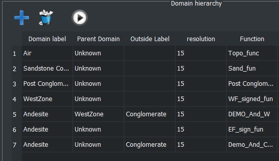
First we needed to model the units not affected by faults as they pre-dated the faulting. These are the Post-Conglomerate Andesite and the Sandstone cover. Then, again, we used the East and West faults to divide the model space up into 3 zones: West, East and Central. These labels were used to create the sub-domains. Within each of the sub-domains, we modelled the geology separately. The end result can be seen on the right (note that the conglomerate was hidden to better highlight the faulted nature of the base layer). Note how the light-green post-conglomerate andesite and blue sandstone cover are not affected by the faults.
The whole process was described in a single model descriptor:
Summary
In this short article we demonstrated how some of the new tools in Version 4 can be efficiently used to created faulted models. GEOREKA’s flexible approach means complex fault zones can be defined and subsequently used to build complex faulted geological models.
