
Geological models using digital outcrops from photogrammetry
With the incredible explosion of drones on the market, more and more uses are starting to be developed. One of the more straight forward applications is creating a 3D capture of outcrops. Using photogrammetry techniques to reconstruct 3D geological models of the drone footage we can use accurate surface information.
Drones are already heavily used in the industrial minerals industry where they are used to produce highly detailed DTM’s (digital terrain models) for measuring stockpiles and up-to-date mine surveys for planning. I believe photogrammetry can also be a real asset to any stage of an exploration project. It provides a lot more information than just a surface or some photos. Especially if you imagine multispectral or hyperspectral information being included.
Photogrammetry without drones
If drones are not available or not practical (you need a lot of batteries and chargers) in remote areas, why not use your normal camera instead? Photogrammetry is not constrained to be used only by drones, it can be applied to any camera, even video cameras. So, instead of flying over the area of interest you can take lots of pictures from the ground (make sure there is at least 60% overlap between neighboring images) or use a video camera. You could even use the camera in your phone. Contact us if you would like to know more about this.
From outcrop to geological models
The big advantage with photogrammetry it that the result will be a 3D model of the surface rather than a stack of photos. That 3D model can then be used directly for creating a 3D geological model. That is what we will demonstrate in this little article.
Assuming you managed to create or retrieve a 3D outcrop model from your area of interest, how can you use it for early stage geological models? First, you will need to be able to import it. For that, most photogrammetry software will allow you to export the outcrop as an OBJ file with associated MTL file and images. All of those are needed to get the best effects. The OBJ contains the triangulated surface and points of the reconstructed outcrop. The MTL file describes the ‘material’ and references the images to project onto the triangulated surface. These images are not the original photos, but are texture images. Textures are widely used in 3D modeling to give the appearance of realistic structures and colors. At the moment of the writing GEOREKA can only handle a single texture image, but will be updated to handle multiple texture files.
Importing an OBJ with the associated MTL and images will show a triangulated surface that looks like a real-life representation of the outcrop (data courtesy of: Mauricio Baquero, Corporacion Geologica Ares, Colombia).
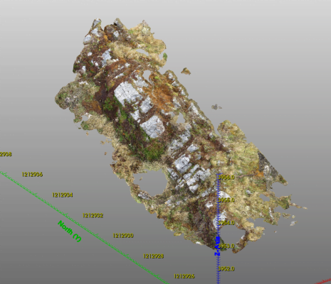
As you can see, the 3D outcrop with its texture and thus the color information provides a lot more information than just a triangulated surface:

After import the outcrop can be used to digitize features like bedding. In this example we demonstrate how a contact is digitized so it can be used for creating a geological model.
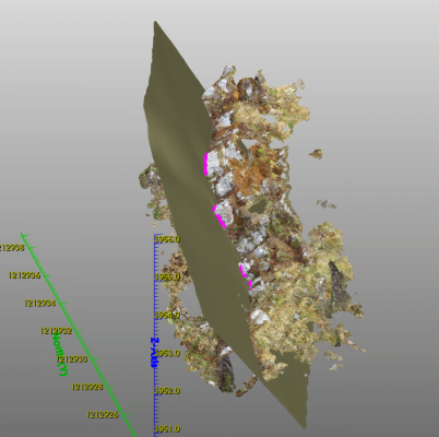
Typically the outcrop only shows patches of the bedding surfaces. To create a complete triangulated surface for it, we digitize the areas where the bedding is visible in the outcrop. In this case we have digitized four parts (four strings) by selecting the outcrop as the surface to draw on. We simply trace over the contact and add each string to our polyline object. By default the polyline will get an orientation for each point, also called the point normal. The point normal is used in implicit modelling techniques to construct a triangulated surface through the points. In this case the normals are pointing in the direction of the bedding plane and will not result in our desired surface. Therefore, we have to re-orient them by looking down-dip at the contact and aligning the orientation (a topic for another day, but roughly we align the point normal with the younging direction of the beds).

When the point normals are set for all four strings it is time to create a contact from them. To this end we use a simple linear implicit modelling technique that will extend the triangulated surface all the way to the model extents. Due to a bit of a step-like shape in the resulting surface we apply an additional smoothing step to reduce the step in the surface and have a more even result. The end-result is a nice continuous smooth contact through our digitized strings.
The only thing left to do is to clip the contact against the original outcrop. That is what we do in the final step to give us our end result:

Now we have an outcrop with a bedding plane that we can use to build a 3D geological model. For a full geological model we would repeat these steps for the other bedding planes, but is beyond the scope of this article.
I hope this article was helpful and will give you some ideas about how photogrammetry can be used even at an early stage in exploration to build 3D models. If you have any questions, please don’t hesitate to contact us.